
News & Events

Electrical Insulation Material Selection: How to Choose the Right Insulation Barrier
July 21,2026
Choosing a flame-retardant barrier is not only about dielectric strength or a UL 94 rating.
In real-world electrical equipment, the right insulation material must balance voltage requirements, thermal exposure, space constraints, compliance, fabrication method, and assembly reliability.
This guide explains how engineers can evaluate flame-retardant electrical insulation barriers for power supplies, EV battery packs, industrial controls, data center equipment, and other demanding applications.
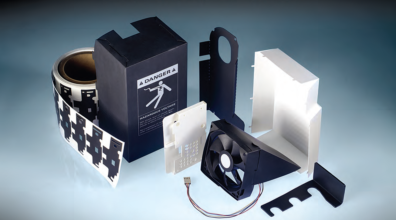
▲ Examples of fabricated insulation barriers, covers, liners, and internal components used in electrical and electronic assemblies.
What Is a Flame-Retardant Electrical Insulation Barrier?
A flame-retardant electrical insulation barrier is a material or fabricated component placed between conductive elements, circuits, busbars, housings, battery modules, or structural parts to provide electrical separation and help reduce flame-spread risk.
The right barrier material should be selected based on how it performs after cutting, folding, fastening, forming, or installation inside the final product.
Common Barrier Functions
- Electrical Isolation: Spacers or separators in dense assemblies
- Electrical Insulation: Insulation liners for housings or modules
- Internal Components: Folded or formed insulation parts
Key Material Selection Factors
When selecting a flame-retardant electrical insulation barrier, engineers should evaluate the complete installed condition, not only a single datasheet value. Key factors include insulation margin, flame-retardant performance, thermal and mechanical stability, and how the material performs after fabrication and assembly.
01
Insulation Margin
The barrier must provide sufficient electrical separation under the actual voltage and spacing conditions of the equipment.
Review focus: dielectric strength, creepage distance, clearance, contamination exposure, edge condition, and required insulation margin.
02
Flame-Retardant Performance
Flame rating should be evaluated together with material thickness, product geometry, and the required certification path.
Review focus: UL 94 rating, material thickness, UL Yellow Card information, and whether system-level validation is still required.
03
Thermal and Mechanical Stability
The material must maintain its shape and insulation coverage near heat-generating components, moving parts, or compression points.
Review focus: operating temperature, thermal aging, vibration, abrasion, compression, and contact with sharp edges or fasteners.
04
Fabrication and Assembly Fit
The selected material must remain functional after die-cutting, scoring, folding, forming, fastening, or installation as a finished part.
Review focus: bend areas, holes, tabs, formed features, tolerance stack-up, assembly repeatability, and final geometry coverage.
Engineering note: A datasheet value does not automatically represent the installed condition. Bends, holes, tabs, fasteners, compression points, and edge contact can all change how the insulation part performs in the final assembly.
A Practical Selection Path for Engineers
The best material choice usually starts with the design risk, not the material list. Use the following sequence to narrow the options before moving into detailed validation.
STEP 01
Define the Electrical Risk
Confirm voltage, creepage distance, clearance, contamination risk, and the insulation margin required in the final assembly.
STEP 02
Confirm Flame and Compliance Needs
Review flame rating, material thickness, UL Yellow Card information, and certification requirements that apply to the product.
STEP 03
Check Thermal and Mechanical Exposure
Consider operating temperature, hot spots, thermal cycling, aging, vibration, compression, abrasion, and nearby sharp edges.
STEP 04
Review Fabrication and Assembly Fit
Confirm whether the part must be die-cut, scored, folded, formed, fastened, or repeatedly installed in production.
STEP 05
Validate the Final Fabricated Part
Test the completed barrier part in the actual geometry, tolerance stack-up, operating condition, and production assembly process.
Formex Material Options at a Glance
Use the table below to compare the typical construction, flame rating, RTI, CTI, available thickness range, and distinguishing features of the Formex material series.
| Series | Type | Regulation | Construction | Color | UL 94 Flammability Rating |
RTI | Thermal Conductivity |
CTI | Thickness [mm] |
Remark | |
|---|---|---|---|---|---|---|---|---|---|---|---|
| Formex® GK | PP | RoHS | Single-layer | NC | BK | V-0 & VTM-0 | 115°C | / | 600V PLC 0 |
0.127~3.2 | |
| Formex® GS | PP | RoHS | Single-layer | NC | / | V-0 & VTM-0 | 115°C | / | 600V PLC 0 |
0.25, 0.43, 0.76 | Anti-static |
| Formex® GL | PP | RoHS | Single-layer | NC | BK | V-0 & VTM-0 | 125°C | / | 600V PLC 0 |
0.25, 0.43 | |
| Formex® EP | PP | RoHS | Single-layer | NC | BK | V-0 & VTM-0 | 110°C | / | 600V PLC 0 |
0.25~1.57 | Economical |
| NEWFormex® TCI | PP | RoHS | Single-layer/ Multi-Layer |
/ | BK | V-0 & VTM-0 | 120°C | 1.0 W/(m·K) |
600V PLC 0 |
0.2, 0.25, 0.43, 0.76 | High TC |
| Formex® N3 | PC | Non-Hal | Multi-Layer | NC | BK | V-0 & VTM-0 | 130°C | / | 300V PLC 3 |
0.2, 0.25, 0.43 | Thickness Reduction |
| NEWFormex® E3 | PC | PFAS Free Non-Hal |
Multi-Layer | NC | BK | VTM-0 | 140°C | / | 300V PLC 3 |
0.2, 0.25 | PFAS Free Non-Hal |
Common Failure Modes to Avoid
Many insulation failures occur because the material was selected from datasheet values alone, without enough attention to the installed condition. The same material may perform differently after cutting, folding, compression, installation near heat sources, or exposure to contamination.
Surface Tracking
Dust, moisture, flux residue, or conductive particles can reduce surface resistance. When this occurs between different electrical potentials, a tracking path may form along the insulation surface and reduce the intended creepage protection.
Mechanical Puncture
Sharp metal edges, burrs, fasteners, vibration, or compression points can cut into thin insulation barriers. This risk should be reviewed after the material is converted into its final part geometry and installed in the actual assembly.
Thermal Deformation
Heat can cause softening, warpage, shrinkage, or loss of barrier coverage, especially near power electronics, busbars, transformers, relays, or battery cells. Materials should be checked against both continuous operating temperature and peak temperature conditions.
Assembly Misfit
Poor geometry, loose fit, feature misalignment, or tolerance stack-up can leave conductive areas exposed or reduce the intended clearance. The final fabricated part should be checked in the real assembly position rather than judged only from a flat material sample.
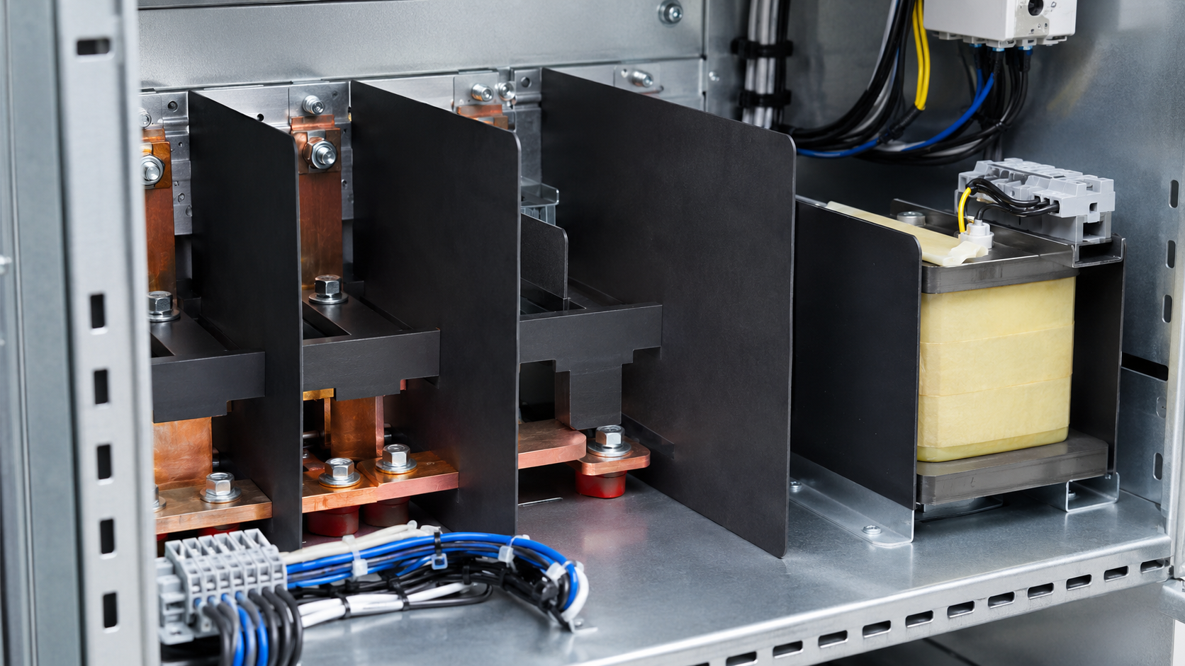
▲ In real assemblies, insulation barriers must meet electrical spacing, mechanical geometry, thermal exposure, and production requirements at the same time.
Application Fit
Flame-retardant electrical insulation barriers are used differently depending on the application. The right material choice depends on what the barrier must isolate, how it is assembled, and what operating stress it must survive.
APPLICATION 01
Power Supplies
Internal barriers can separate primary and secondary circuits, cover exposed conductive areas, and help maintain insulation spacing.
Selection focus: dielectric strength, flame rating, thickness, and repeatable assembly.
APPLICATION 02
EV Battery Packs
Battery modules may require cell-, module-, or pack-level barriers in compact high-voltage designs.
Selection focus: voltage, heat, vibration, formed geometry, and certification requirements.
APPLICATION 03
Industrial Controls
Barriers can help prevent contact between terminals, relays, busbars, conductive parts, and enclosure structures.
Selection focus: mechanical durability, fit, flame rating, and installation consistency.
APPLICATION 04
Data Center Equipment
Insulation liners or internal barriers may be used around data center power distribution areas.
Selection focus: electrical safety, flame performance, fit, and installation consistency.
Practical Checklist Before Final Material Selection
Before finalizing a flame-retardant electrical insulation barrier, confirm that the material, thickness, geometry, and fabricated part all match the actual operating and assembly conditions.
01What voltage must the barrier isolate?
02What creepage and clearance distances apply?
03What flame rating or compliance path is required?
04What thickness can the design tolerate?
05What continuous and peak temperatures are expected?
06Will the part be flat, folded, scored, or formed?
07Are there sharp edges, burrs, or fasteners?
08Will moisture, dust, or contamination be present?
09Can the part be assembled repeatably in production?
10Has the final fabricated part been validated?
FAQ: Flame-Retardant Electrical Insulation Barrier Selection
What is the most important property when selecting an electrical insulation material?
There is no single property that determines the correct choice. Dielectric strength matters, but engineers must also evaluate voltage, creepage, clearance, flame rating, temperature, thickness, mechanical durability, fabrication method, and final assembly conditions.
Does a UL 94 flame rating mean the material is approved for my product?
No. UL 94 describes material burning behavior under specific test conditions. The final product may still require system-level evaluation, correct thickness selection, proper geometry, and compliance review based on the applicable standard.
Why ITW Formex®?
- Superior Material Properties
- Superior Ability to Meet Stringent Insulation Requirements for Diverse Applications (Thermally-Conductive, High Temperature-Resistance, Static Dissipation, etc.)
- Trusted Quality
- Industry-Recognized Brand Name
- Innovative Solutions
- Customer-Backed Innovation Leadership Based on Over 40 Years of Application Expertise in Insulation Materials
Need help selecting the right flame-retardant barrier?
ITW Formex can help review your voltage, temperature, thickness, fabrication, and assembly requirements before your design is finalized.
Contact an ITW Formex Engineer